
Thrust Chamber Assembly
The thrust chamber assembly (TCA) is the part of the rocket which ingests propellant, combusts it, and exhausts gas to produce thrust. It consists of an injector, combustion chamber, and nozzle.
The most common type of chamber for standard liquid rockets is the heatsink. This means that it is not cooled in any way; rather, it is intended to absorb heat for a limited amount of time. Heatsink chambers are heavier than an equivalently sized ablative or regenerative cooled chamber, but extremely simple to make and require no maintenance. Aluminum heatsink chambers are made possible by short burns times and a low mixture ratio which sacrifices performance efficiency to lower combustion temperature dramatically.
The figure below depicts a typical thrust chamber assembly, where the nozzle is made from solid round bar and the barrel section from extruded tube, with a flexible graphite gasket seal at the interface. The chamber can also be made in a single piece (monolithic) from solid round bar if desired. The chamber may include a throat insert, a separate piece made of a more heat-resistant material like copper or graphite which replaces a small portion of the nozzle around the throat. This increases chamber survivability against longer burn times or more intense operating conditions.

Standard thrust chamber assembly, with scrintle injector and throat insert (cartridge igniter omitted)
The exact design of an injector is open to personal choice, but it will usually take the basic form of a groove-manifold (see figures below). Groove manifold injectors are simple lathe parts with minimal drilling required. The actual injection elements themselves may be simple impinging doublets, a scrintle, or a more complicated scheme such as coaxial shear.
Basic groove-manifold scrintle injector (Shown in section plane with injection orifices)

Basic groove-manifold scrintle injector (Shown in section plane with fuel inlet and igniter pass-through holes)
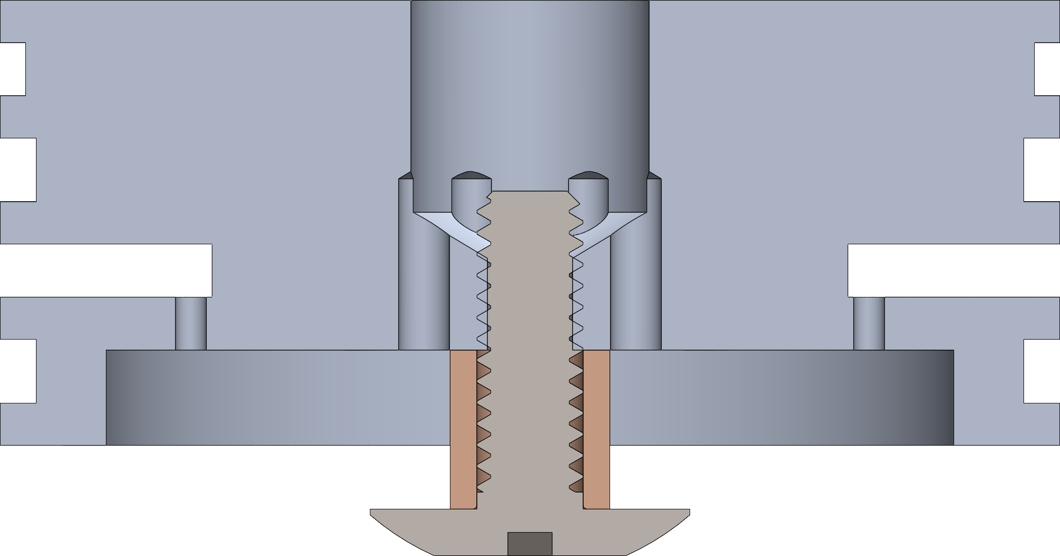
In addition to the radially-bolted retention method used in the propellant tank, the thrust chamber assembly may be retained with axial compression as shown in the figure below. In this method, two flange plates clamp the injector and chamber with threaded rods and fastening hardware. Since the flange plates can be laser- or waterjet-cut from flat metal plate, they are very economical; they also eliminate the need for fastening features on the chamber and injector themselves, which greatly reduces the machining time and required precision. Note that the combustion chamber can be made from one or two pieces, but the flange plate clamping works the same either way.
The igniter is responsible for initiating combustion. It must provide a large heat input to overcome the energy barrier to nitrous decomposition and break it down into nitrogen and oxygen, which then burns with fuel to sustain combustion. Ignition must be highly reliable, and the best method to achieve this is with a solid propellant cartridge igniter (see below). The benefit of a cartridge igniter over igniters inserted through the throat is that it moves the igniter itself away from the liquid propellant stream; the blast of cold propellants is capable of forcibly ejecting an igniter or simply extinguishing the igniter flame. With a cartridge igniter, where a solid propellant (typically an Estes blackpowder motor or similar) is contained within a housing stood off from the chamber, there is no possibility that either of these scenarios can occur - in fact, in all cases where the E-match has fired and both propellant valves opened, cartridge igniters have demonstrated 100% reliability in Half Cat Rocketry motors.

Cartridge igniter, made with off-the-shelf components
The cartridge igniter may be threaded into either the injector or chamber wall. Placement on the injector is better for aerodynamics because the cartridge will be fully within the profile of the vehicle, although it can be challenging to route the igniter through-hole between the central oxidizer port and the fuel groove-manifold. Placement on the chamber wall is typically only possible in heatsink chambers, which are thick enough to drill and tap a port into.
Cartridge igniters also make convenient chamber pressure transducer locations. Since the igniter is open to the combustion chamber, a transducer on the cartridge will read chamber pressure; since it somewhat removed from the chamber, the sensor itself it protected from high heat flux and is able to survive the full duration of the burn.
HCR-1100 standard for amateur liquid rocket thrust chamber assemblies
The Thrust Chamber Assembly shall consist of an injector, combustion chamber, nozzle, igniter, and may include an ablative thermal liner inside the combustion chamber.
The injector shall include threaded ports to permit ingestion of oxidizer and fuel from the propellant feed system, contain any number and shape of orifices to permit injection of oxidizer and fuel into the combustion chamber, and be sealed to the combustion chamber with radial elastomeric O ring(s).
The nozzle shall include a throat to exhaust propellant to ambient and be radially sealed to the combustion chamber by either elastomeric O-ring(s) or a flat flexible-graphite gasket which may only be used in conjunction with flange plate retention. If a thermal liner is included in the combustion chamber, the nozzle shall also seal to it in addition to the combustion chamber. The nozzle may consist of either A) a single piece or B) separate nozzle carrier and throat insert pieces.
A. Single piece nozzles shall be made from aluminum or copper.
B. Nozzle carriers shall be made from aluminum or copper. Throat inserts shall be made from 300-series stainless steel, any grade or alloy of copper, 600- or 700- series nickel superalloy, graphite, or phenolic-based composite material.
The combustion chamber shall be made from aluminum or copper.
The injector, nozzle, and combustion chamber shall be retained against internal pressure by either A) retaining rings or B) flange plates.
A. Radial fasteners shall pass through clearance holes in the wall of the combustion chamber and through the retaining rings, which may be separate pieces or integral the injector/nozzle, and may be secured either with nuts placed on the inner diameter of the retaining ring or by threading into the tapped holes in the retaining ring itself.
B. Axial rods, which may be all-thread or partial-thread, shall pass through clearance holes in the faces of the flange plates, which may be separate pieces (recommended) or integral to the injector/nozzle, and shall be secured with nuts threaded onto the rods and tightened onto the face of the flange plate such that the injector and nozzle are compressed in contact with the combustion chamber.
As an exception to the above, the combustion chamber and nozzle may together consist of a single piece made from any alloy of either aluminum or copper and be sealed and retained to the injector in same manner as described previously.
The igniter shall be a cartridge made of aluminum, brass, or stainless steel threaded into a port on either the injector or combustion chamber to permit discharge of hot gas into the combustion chamber. The igniter may consist of one piece or multiple separate pieces. The igniter cartridge shall contain solid propellant which is started by an electronic initiator that is triggered by a ground-side ignition command.