
Propellant Tank
Fuel and oxidizer must be stored in a pressure vessel: the propellant tank. A question often asked by teams and individuals looking to build a liquid rocket is where to get tanks from: The answer is simply to make them, as the resulting product will be lighter, cheaper, and easier to use than a commercially manufactured pressure vessel.
The answer is also related to another frequently asked question: How are the fuel and oxidizer pressurized? This single question, more than any other, will determine the level of complexity and scope in a liquid rocket project, and can make or break it before it begins. Thus, in standardizing a simple liquid bipropellant architecture, the pressurization scheme was made an entirely passive byproduct of the physical design.
Dual-Acting Vapor Pressurization is a method which requires no additional gases or components to pressurize either the fuel or oxidizer. The concept is simple: A “floating” piston sits inside the propellant tank, free to move when pushed. It is exposed to liquid N2O on one side, and liquid fuel on the other, with seals in between to prevent them from mixing. N2O’s vapor pressure is quite high – in the hundreds of psi for typical temperatures – meaning that it does not need a pressurant gas. Since the N2O is pushing on the piston, that pressure is applied to not only itself but the fuel as well. This means that when the main propellant valves open, both liquids are forced out.
Because N2O is stored as a saturated liquid, it always wants to maintain a specific pressure corresponding to its bulk temperature. Thus, it rapidly boils off some liquid while the tank drains to maintain pressure until all liquid has been expelled. In the boiling process, it expends some internal energy in the form of temperature. As it cools down during expulsion, the corresponding saturation temperature drops, and the tank pressure decays. The thermodynamics work out such that the pressure decays over time to a final value which is always about 50-70% of the initial. Therefore, it can be seen that the energy to maintain pressure – rather than being provided by a pump or compressed gas – is the heat energy stored within the liquid oxidizer itself.
All standard liquid rockets include a small hole called a static vent at the top of the N2O tank. It has two critical purposes:
Oxidizer loading. Without a way for gas to escape from the tank, only a little bit of N2O would fill before it became fully pressurized and nothing more could enter (a pressure gradient is required for fluid to move). Therefore, the static vent allows air and N2O gas to escape and be replaced with liquid drawn out of the supply bottle.
Safety. The static vent ensures that in any scenario there will always be a way for N2O to eventually boil out and depressurize. Since the static vent is quite literally a hole in the tank, it can never fail into a condition where pressure gets trapped in the system.
The ends of a standard liquid bipropellant tank are formed by O-ring sealed bulkheads with fluid fittings and a retaining ring held in by radial bolts. The bulkheads and retaining rings may be combined into a single part, but separate pieces are generally easier and cheaper.
Another rather unique aspect of most standard Half Cat rockets is the tank arrangement. In most designs, oxidizer is stored below the piston and fuel above it, so that the propellant tank can be formed from a single metal tube. This is called a stacked tank. It contrasts with concentric tanks, where the fuel tank sits completely inside the oxidizer tank and both outlets are at the bottom end. As a consequence of the stacked tank design, fuel first travels up out of the top bulkhead, then back down through an external downcomer. It has no detrimental effect on the system except for a minor fuel pressure loss through the downcomer. Furthermore, this has been found to act as a sort of natural filter for large particulates in the fuel tank, which sink to the bottom.

Stacked propellant tank with upwards-moving piston (to the right, as pictured), after manual fueling and prior to oxidizer loading operations. The fuel tank is sealed and the rocket may be handled without hazard as long as the fuel valve is kept closed.

Stacked propellant tank with upwards-moving piston (to the right, as pictured), at an arbitrary time during oxidizer fill. The static vent is located just below the oxidizer side of the propellant piston (on the left of the piston, as pictured). Even though the oxidizer tank is sealed, the rocket is hazardous at any time when pressure or oxidizer are present. No personnel are allowed to be near the propellant tank at this point, and must remain away until it has completely depressurized.
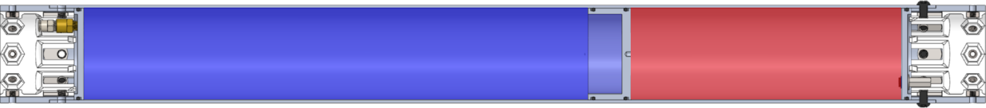
Stacked propellant tank with upwards-moving piston (to the right, as pictured), prior to starting operation. Note that in reality, the propellant tank must be upright relative to gravity, so that the oxidizer (blue) drains to the outlet at the bottom (on the left, as pictured) and fuel (red) drains to the outlet at the top (on the right, as pictured).
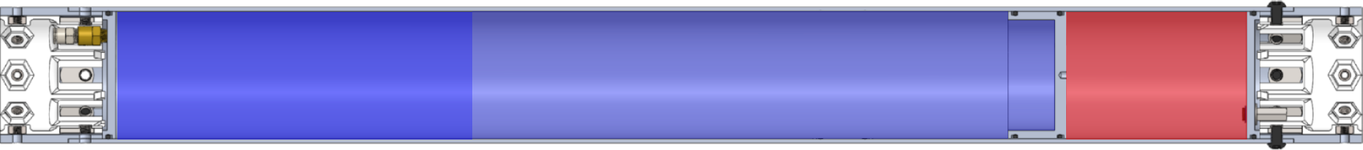
Stacked propellant tank with upwards-moving piston (to the right, as pictured), at an arbitrary time during operation. In a stacked tank configuration, the piston moves upwards to force fuel out while oxidizer drains. The drained portion of the tank is replaced by gaseous oxidizer.
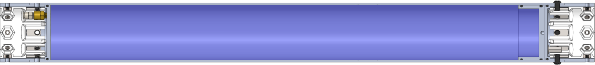
Stacked propellant tank with upwards-moving piston (to the right, as pictured), after exhausting all liquid fuel and oxidizer. Once all liquid has been expelled, the remaining pressurized gas discharges through the oxidizer outlet.
HCR-1100 standard for amateur liquid rocket propellant tanks
The Propellant Tank shall be made from aluminum alloy round tube (recommended) or pipe, with bulkheads at each end radially sealed with elastomeric O-rings and retained by radial fasteners. The bulkheads shall include threaded ports for fittings to permit discharge of oxidizer and fuel from the tank to the propellant feed system, as well as filling of the oxidizer tank from the ground support system. The bulkheads shall be supported against internal pressure by a retaining ring, which may be a separate piece (recommended) or integral to the bulkhead. Radial fasteners shall pass through clearance holes in the tank wall and through the retaining ring and may be secured either with nuts placed on the inner diameter of the retaining ring (recommended) or by threading into tapped holes in the retaining ring itself.
The oxidizer tank may comprise the lower portion of a tank consisting of a single tube (stacked tanks; recommended) or a larger-diameter outer tube concentric to the inner tank tube (concentric tanks), with its outlet on the aft bulkhead. The oxidizer tank shall always have a static pressure vent drawing fluid from the forward end of the oxidizer tank. The static vent may be either a hole drilled directly in the side of the oxidizer tank or a hole drilled in a fitting that is stood off from the oxidizer tank. Siphon tubes may be used to locate the static vent in a position aft of the oxidizer tank. The internal fluid path from oxidizer tank to static vent shall never be impeded by valves, seals, or other obstructions.
The fuel tank may comprise of the upper portion of a tank consisting of a single tube, with its outlet on the forward bulkhead such that fuel is expelled by upwards motion of the propellant piston (stacked tanks; recommended) or a smaller-diameter inner tube concentric to the outer tank tube, with its outlet on the aft bulkhead such that fuel is expelled by downward motion of the propellant piston (concentric tanks).
The fuel and oxidizer shall be separated by a piston, which is free to slide inside the tank in order to expel the fuel using the pressure applied by the oxidizer vapor. The length of the piston shall be not less than one half of the inner diameter of the tube, and shall include a minimum of two elastomer seals between the fuel and oxidizer. Pistons may use O-rings (recommended) or other types of seals such as U cups, X-rings, square rings, T-rings, or similar. If directional pressure-assisted seals such as U-cups are used, they shall be oriented in opposite directions, such that each seal is assisted by the pressure of the propellant on the side of the piston to which it is closest. Non-elastomer seals including PTFE O-rings, PTFE spring-energized seals, metallic seals, or braided packing seals shall not be used on propellant pistons.
The oxidizer tank shall include a minimum of 5% ullage volume in case of sudden, rapid heating. Ullage may be formed in a stacked tank either by a set distance between the level of the static vent (or siphon tube) and the oxidizer side of the piston or by a hollowed-out pocket in the piston. Ullage may be formed in a concentric tank by any arrangement that forms a cavity which liquid cannot rise to during fill.